Introduction
Stream Tools Utilities HelpStream Tools Autodesk® Civil 3D® Plug-in extends the functionality of Civil 3D by automating the process of creating breaklines to define a stream channel with a riffle/pool or step/pool sequence.
Command Overview
There are three commands included with the Stream Tools Plug-in.
CREATESTREAMBREAKLINES

This is the command used to define the channel cross-sections and the profile characteristics such as pool drop.
GENERATEREFERNCEPROFILE

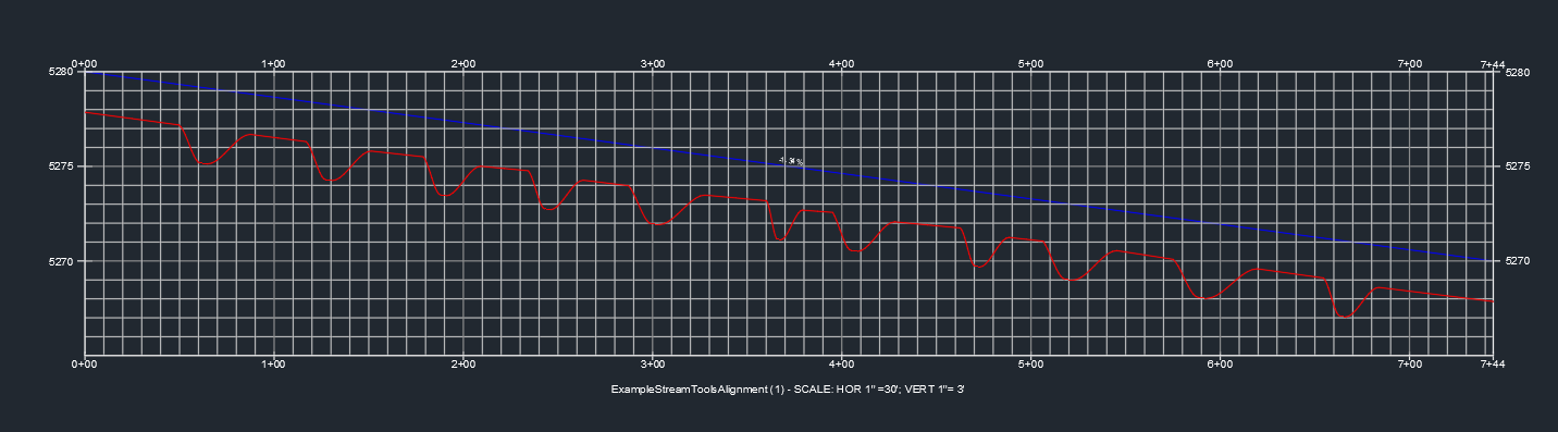
This command is used to generate the reference bankfull profile so that the user may modify the profile to include custom drops and adjustments. This option is typically used after the CREATESTREAMBREAKLINES tool has been used and values saved to the alignment. The user can then manually adjust the profile to include drops for structures such as "J-hooks".
CREATEPROFILEFROM3DPOLY

This command is used to create a profile from a 3d polyline. This tool was created to facilitate the plan production process where thalweg profiles are needed. When this 3d polyline is made into a true Civil 3D profile the full label functionaly is available
How To
The following video shows how Stream Tools is used to develop the stream design surface. The entire design series can be viewed here. Please remember to like, subscribe, and comment to help support the development of more videos and the Stream Tools software.
Installation
Step 1: Stream Tools is installed from an installation file downloaded through the Autodesk App Store. Before installing Stream Tools please close Civil 3D. If there is a previous version of the tool installed on your machine you may need to remove this first.
If you have a pervious version on your machine version go to the Installed apps in Windows and scroll down to find the Stream Tools Installer, click the … and select uninstall. Now you should be able to install using the standard installer.
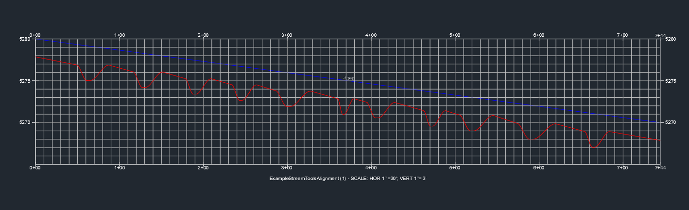
Step 2: An alignment and bankfull profile are needed before Stream Tools can run. The alignment is expected to be drawn using the Alignment Layout Tools as a Tangent-Tangent (with curves) alignment. The tool roughly assumes that the Tangent sections of the alignment represents riffles and the curve section represents the run, pool, and glide sections. The profile is drawn using the Profile by Layout tool, it is expected that the proifle be defined for all stations along the alignment.
Step 3: Run the CREATESTREAMBREAKLINES command by either typing CREATESTREAMBREAKLINES into the command line or clicking on the Stream Tools Panel on the Add-ins tab.
Methods
The user interface will then ask you to select the method desired for the process:
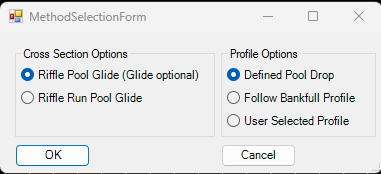
Starting with the Cross Section Options on the left there are two options:
1. Riffle Pool Glide (Glide optional) is the first option. Use this option when the target design holds the pool flat. This option is typically appropriate for stream with slopes less than 2%. Using this option the riffle slopes will vary based on the proportion of riffles and pools and the user defined maximum drop over the all the pools. For the pool to be flat the glide cross section max depth must equal the riffle max depth. Because of the proration methods the glide will be shallower than the cross section shows.
2. Riffle Run Pool Glide is the second option. This option is used to define the cross-section shape at each of those four positions throughout the design. The difference in thalweg depth from end of riffle to head of glide will vary based on pool length and slope. This option is typically appropriate for streams with slopes greater than 2%.
Moving to the right side there are three options:
1. Defined Pool Drop is the first option. This is the original option for creating riffle pool channel designs. This process adjusts the channel cross-section so that the riffle is defined by the bankfull cross-section but the rest of the profile is defined so that the pool is held flat, or with a set user defined drop. This option is usually paired with the first option on the left.
2. Follow Bankfull Profile is the second option. This option references the bankfull profile as drawn. This option works best for systems with slopes greater than about 2% and is usually paired with the Riffle Run Pool Glide option. Pool drop may vary from pool to pool.
3. User Selected Profile. This option would be used to incorporate drop structures into a channel design. This option is usually used after a run of the program has been completed using option 1. This allows for further refinement of the channel design.
The CREATEREFERENCEPROFILE would typically be used as the starting poing.
NOTE! No matter which option is selected the outside two breaklines always follow the user input bankfull profile. It is possible to create a condition where the inside breaklines have elevations above the outside breaklines.
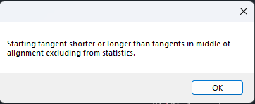
Step 4. The add-in will prompt the user to select the alignment and the bankfull profile. The add-in will perform some basic checks. The program expects the profile to be defined for all stationing along the alignment. The program will also check to see if the beginning or ending tangent section is longer or shorter than the maximum or minimum. If this is the case these sections will not be included in the average on the Introduction Screen of the main interface. This is because often projects have tie-in requirements that require manual tie-in consideration.
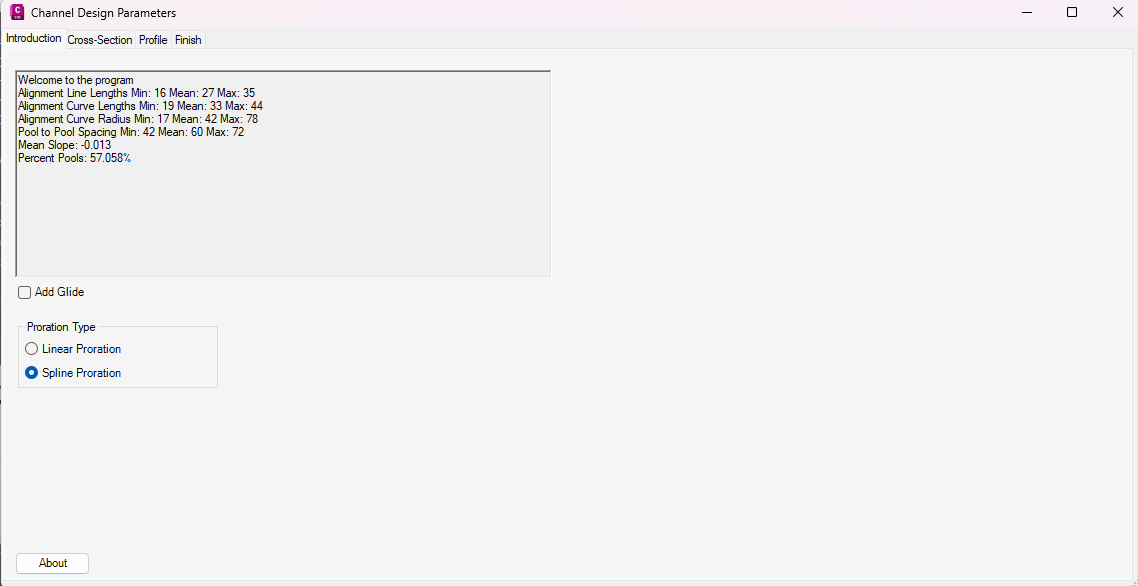
Step 5. The introduction screen provides an overview of the information from the alignment and the profile. This is a good place to compare the information to your design objectives to evaluate if the alignment is correct. This tool does not replace looking down the alignment with your tools and design parameters as well. You can also decide whether to include a glide or not on this screen.
NOTE! In Version 3.1 the option for spline or linear proration was made available. Spline proration tends to create better grading within the glide region. Linear proration creates simpler planset labels.
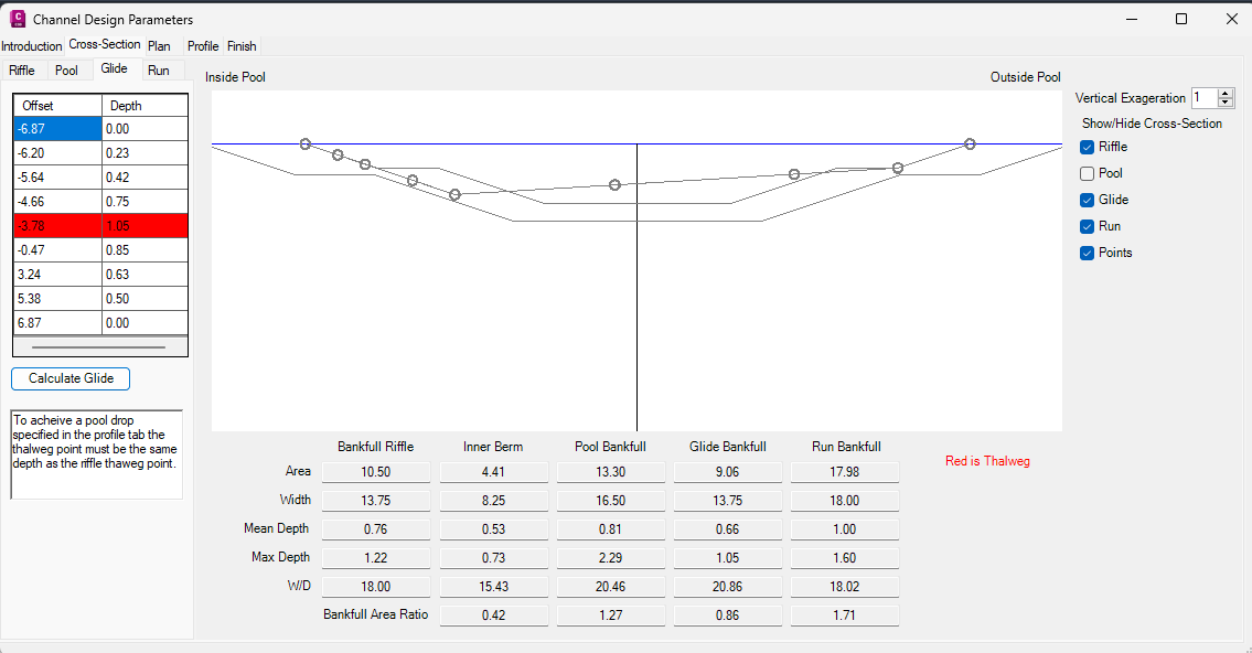
Step 6. The Cross-Section tab is where the channel cross-sections are defined. Depending on which option was selected in Step 3 and 5 will determine how many cross-sections appear on the left set of tabs.
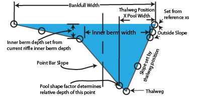
Note! Each cross section may be manually edited in the table. The red box marks the thalweg position. Depth is measured from bankfull.
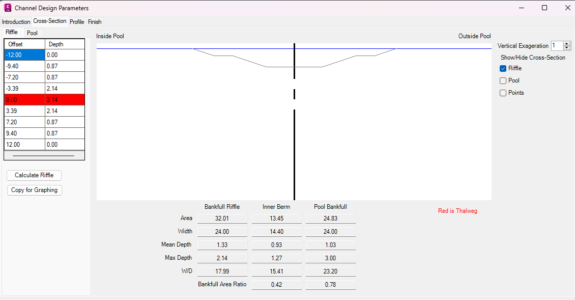
1. Riffles have a single calculator.
2. Pools have a two calculators and this tab shows the max depth ratio and pool width ratio on the tab for reference.
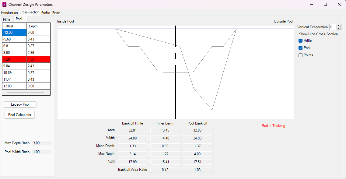
The legacy pool calculator is the first calculator that was created.
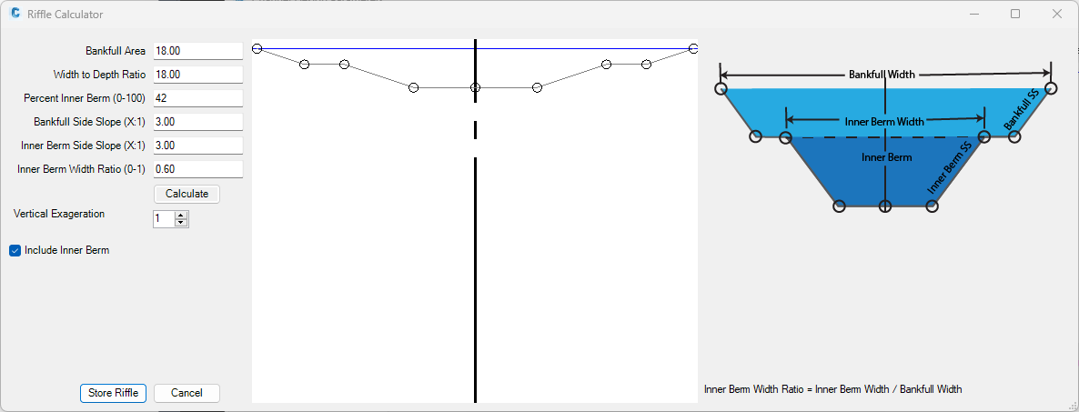
Pool Calculator is the revised pool calculator that utilizes more standard inputs. The reference image shows the definition of where each of the terms are measured. The user has the option to change the way the measurements are displayed whether based on ratios or project units. Note ratios require the riffle cross-section be defined first.

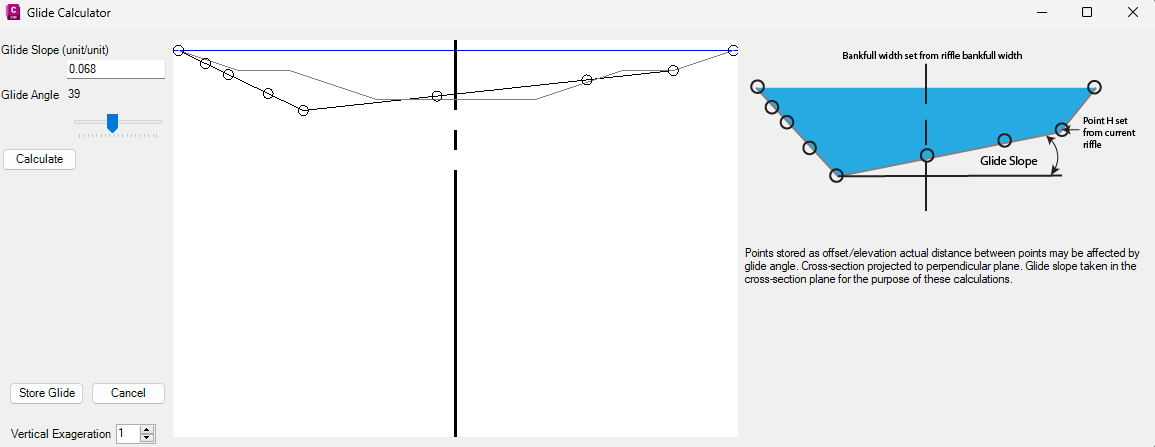
3. Glides have one calculator.
Note! If the Defined Pool Drop option is used the thalweg depth has to be the same as the riffle depth to acheive the desired results. If the Follow Bankfull Profile is selected the depth should be set based on the desired proportions for the riffle to avoid a "kink". Glides are the only cross-section at this time that can be placed at an angle.
4. Runs don't have a calculator. If you have suggestions please pass them along and we will evaluate incoproating them.
Step 7. Plan adjustments are available if there is a glide included in the design.
Step 8. Profile adjustments may be made. Pool position defines where the pool cross-section is located in the curve as a proportion. Moving the pool position closer to the beginning will steepen the run moving the pool position farther into the glide will steepen the glide. The pool flat propotion sets how much of the curve will be defined directly by the pool cross-section. Maximum pool drop will set each of the pools to have the drop specified.
Note! The pool drop option is used for compensating for structures that allow drop over them. Structures may also be incorporated by using the "User Defined Profile"
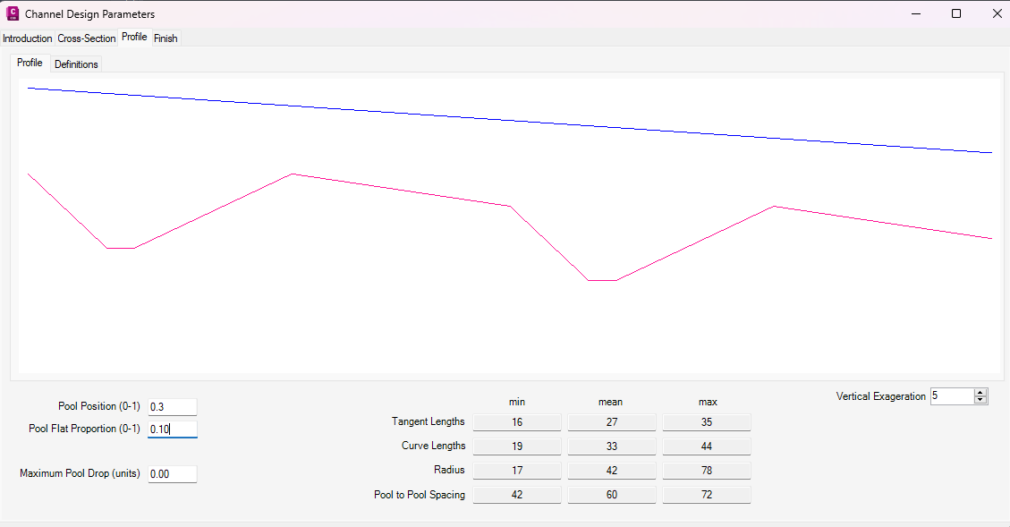
Below is an example of the difference in the generated results with 0.5 ft pool drop and 0.0 ft pool drop.
With 0.50 ft pool drop
With 0.00 ft pool drop